Background
RENAC N3 HV Series is three-phase high voltage energy storage inverter. It contains 5kW, 6kW, 8kW, 10kW four kinds of power products. In large household or small industrial and commercial application scenarios, the maximum power of 10kW may not meet the needs of the customers.
We can use multiple inverters to form a parallel system for capacity expansion.
Parallel connection
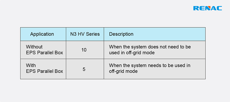
The inverter provides the parallel connection function. One inverter will be set as the “Master
inverter” to control the other “Slave inverters” in the system. The maximum number of inverters paralleled is as follows:
Maximum number of inverters paralleled
Requirements for parallel connection
• All inverters should be of the same software version.
• All inverters should be of the same power.
• All batteries connected to the inverters should be of the same specification.
Parallel connection diagram
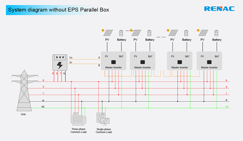
● Parallel connection without EPS Parallel Box.
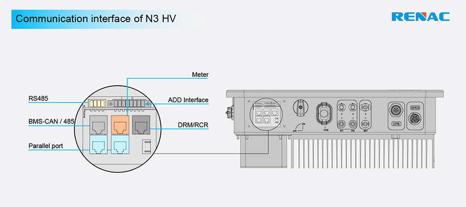
» Use standard network cables for Master-Slave inverter connection.
» Master inverter Parallel port-2 connects to Slave 1 inverter Parallel port-1.
» Slave 1 inverter Parallel port-2 connects to Slave 2 inverter Parallel port-1.
» Other inverters are connected in the same way.
» Smart meter connects to METER terminal of the master inverter.
» Plug the terminal resistance (in the inverter accessory package) into the empty parallel port of the last inverter.
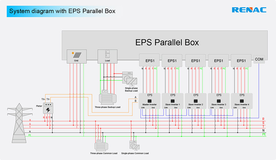
● Parallel connection with EPS Parallel Box.
» Use standard network cables for Master-Slave inverter connection.
» Master inverter Parallel port-1 connects to the COM terminal of the EPS Parallel Box.
» Master inverter Parallel port-2 connects to Slave 1 inverter Parallel port-1.
» Slave 1 inverter Parallel port-2 connects to Slave 2 inverter Parallel port-1.
» Other inverters are connected in the same way.
» Smart meter connects to METER terminal of the master inverter.
» Plug the terminal resistance (in the inverter accessory package) into the empty parallel port of the last inverter.
» EPS1~EPS5 ports of the EPS Parallel Box connects EPS port of each inverter.
» GRID port of the EPS Parallel Box connects to the gird and LOAD port connects the back-up loads.
Work modes
There are three work modes in the parallel system, and your acknowledgment of different inverter’s work modes will help you understand the parallel system better.
● Single Mode: No one inverter is set as a “Master”. All inverters are in single mode in the system.
● Master Mode: When one inverter is set as a “Master,” this inverter enters master mode. The master mode can be changed
to the single mode by LCD setting.
● Slave Mode: When one inverter is set as a “Master,” all other inverters will enter slave mode automatically. Slave mode cannot be changed from other modes by LCD settings.
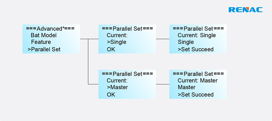
LCD Settings
As shown below, users must turn the operation interface to “Advanced*”. Press up or down button to set the parallel functional mode. Press ‘OK’ to confirm.