Hybrid Inverter
Hybrid Inverter
Hybrid Inverter
Hybrid Inverter
Single Phase, 1MPPT
Single Phase, 1MPPT
Single Phase, 2MPPTs
Single Phase, 2MPPTs
Single Phase, 2 MPPTs
Single Phase, 2 MPPTs
Three Phase, 2 MPPTs
Three Phase, 2 MPPTs
Three Phase, 2 MPPTs
Three Phase, 2 MPPTs
Three Phase, 3 / 4 MPPTs (NEW)
Three Phase, 3 / 4 MPPTs
Three Phase, 10 / 12 MPPTs

WELCOME SERVICE
 On-grid Inverter
 Residential Energy Storage Products
 Commercial and Industrial Energy Storage Products
 Wallbox
 Configuration
 On-grid Inverter
 Residential Energy Storage Products
 Commercial and Industrial Energy Storage Products
 Wallbox
 Configuration
FREQUENTLY ASKED QUESTIONS
-
Q1: Could you introduce Renac power N3 HV series inverter?
RENAC POWER N3 HV Series is three phase high voltage energy storage inverter. It takes smart control of power management to maximize self-consumption and realize energy independence. Aggregated with PV and battery in the cloud for VPP solutions, it enables new grid service. It supports 100% unbalanced output and multiple parallel connections for more flexible system solutions.
-
Q2: What is the maximum input current of this type inverter?
Its maximum matched PV module current is 18A.
-
Q3:What is the maximum amount of parallel connections this inverter can support?
Its maximum support up to 10 units parallel connection
-
Q4: How many MPPT's does this inverter have and what is the voltage range of each MPPT?
This inverter has two MPPTs, each supporting a voltage range of 160-950V.
-
Q5:What is the voltage of the batteries matched with this type inverter and what is the maximum charging and discharging current?
This inverter matches the battery voltage of 160-700V, the maximum charging current is 30A, the maximum discharging current is 30A, please pay attention to the matching voltage with the battery (no less than two battery modules are needed to match the Turbo H1 battery).
-
Q6:Does this type inverter need an external EPS box?
This inverter without external EPS box, comes with EPS interface and automatic switching function when needed to achieve module integration, simplify installation and operation.
-
Q7:What are the protection features of this type inverter?
The inverter integrates a variety of protection features including DC insulation monitoring, input reverse polarity protection, anti-islanding protection, residual current monitoring, overheating protection, AC overcurrent, overvoltage and short-circuit protection, and AC and DC surge protection etc.
-
The inverter integrates a variety of protection features including DC insulation monitoring, input reverse polarity protection, anti-islanding protection, residual current monitoring, overheating protection, AC overcurrent, overvoltage and short-circuit protection, and AC and DC surge protection etc.
This type inverter’s self-power consumption in standby is less than 15W.
-
Q9: What to look for when servicing this inverter?
(1) Before servicing, first disconnect the electrical connection between the inverter and the grid, and then disconnect the DC side electrical (connection. It is necessary to wait for at least 5min or more to allow the inverter’s internal high-capacity capacitors and other components to be fully discharged before carrying out the maintenance work.
(2) During the maintenance operation, first visually check the equipment initially for damage or other hazardous conditions, and pay attention to anti-static during the specific operation, and it is best to wear an anti-static hand ring. To pay attention to the warning label on the equipment, pay attention to the inverter surface is cooled down. At the same time to avoid unnecessary contact between the body and the circuit board.
(3) After the repair is completed, make sure that any faults affecting the safety performance of the inverter have been resolved before turning the inverter on again.
-
Q10: What is the reason for the inverter screen not displaying? How to solve ?
General reasons include:① The output voltage of the module or string is lower than the minimum working voltage of the inverter. ② Input polarity of the string is reversed. The DC input switch is not closed. ③ DC input switch is not closed. ④ One of the connectors in the string is not connected properly. ⑤ A component is short-circuited, causing the other strings to fail to work properly.
Solution: Measure the DC input voltage of the inverter with DC voltage of multimeter, when the voltage is normal, the total voltage is the sum of component voltage in each string. If there is no voltage, test whether DC circuit breaker, terminal block, cable connector, component junction box, etc. are normal in turn. If there are multiple strings, disconnect them separately for individual access testing. If there is no failure of external components or lines, it means that the internal hardware circuit of the inverter is faulty, and you can contact Renac for maintenance.
-
Q11: The inverter cannot be connected to the grid and displays the fault message "No Uility"?
General reasons include:① The inverter output AC circuit breaker is not closed. ② The inverter AC output terminals are not connected properly. ③ When wiring, the upper row of the inverter output terminal is loose.
Solution: Measure the AC output voltage of the inverter with a multimeter AC voltage gear, under normal circumstances, the output terminals should have AC 220V or AC 380V voltage; if not, in turn, test the wiring terminals to see if they are loose, whether the AC circuit breaker is closed, leakage protection switch is disconnected etc.
-
Q12 : The inverter displays a grid error and shows the fault message as voltage error "Grid Volt Fault" or frequency error "Grid Freq Fault" "Grid Fault"?
General reason: The voltage and frequency of the AC power grid are out of the normal range.
Solution: Measure the voltage and frequency of the AC power grid with the relevant gear of the multimeter, if it is really abnormal, wait for the power grid to return to normal. If the grid voltage and frequency are normal, it means that the inverter detection circuit is faulty. When checking, first disconnect the DC input and AC output of the inverter, let the inverter power off for more than 30min to see if the circuit can recover by itself, if it can recover by itself, you can continue to use it, if it can’t be recovered, you can contact NATTON for overhaul or replacement. Other circuits of the inverter, such as inverter main board circuit, detection circuit, communication circuit, inverter circuit and other soft faults, can be used to try the above method to see if they can recover by themselves, and then overhaul or replace them if they can not recover by themselves.
-
Q13 : Excessive output voltage on the AC side, causing the inverter to shut down or derate with protection?
General reason: mainly because of the grid impedance is too large, when the PV user side of the power consumption is too small, the transmission out of the impedance is too high, resulting in the inverter AC side of the output voltage is too high!
Solution: ① Increase the wire diameter of the output cable, the thicker the cable, the lower the impedance. The thicker the cable, the lower the impedance. ② Inverter as close as possible to the grid-connected point, the shorter the cable, the lower the impedance. For example, take 5kw grid-connected inverter as an example, the length of AC output cable within 50m, you can choose the cross-sectional area of 2.5mm2 cable: the length of 50 – 100m, you need to choose the cross-sectional area of 4mm2 cable: length greater than 100m, you need to choose the cross-sectional area of 6mm2 cable.
-
Q14 : DC side input voltage overvoltage alarm, error message "PV Overvoltage" displayed?
Common reason: Too many modules are connected in series, causing the input voltage on the DC side to exceed the maximum working voltage of the inverter.
Solution: According to the temperature characteristics of PV modules, the lower the ambient temperature, the higher the output voltage. The input voltage range of three-phase string energy storage inverter is 160~950V, and it is recommended to design the string voltage range of 600~650V. In this voltage range, the inverter efficiency is higher, and the inverter can still maintain the start-up power generation state when the irradiance is low in the morning and evening, and it will not cause the DC voltage to exceed the upper limit of the inverter voltage, which will lead to the alarm and shutdown.
-
Q15: The insulation performance of the PV system is degraded, the insulation resistance to ground is less than 2MQ, and the fault messages "Isolation error" and "Isolation Fault" are displayed?
Common reasons: Generally the PV modules, junction boxes, DC cables, inverters, AC cables, terminals and other parts of the line to ground short-circuit or insulation layer damage, loose string connectors into the water and so on.
Solution: Solution: Disconnect the grid, inverter, in turn, check the insulation resistance of each part of the cable to ground, find out the problem, replace the corresponding cable or connector!
-
Q16: Excessive output voltage on the AC side, causing the inverter to shut down or derate with protection?
Common reasons: There are many factors affecting the output power of PV power plants, including the amount of solar radiation, the tilt angle of the solar cell module, dust and shadow obstruction, and the temperature characteristics of the module.
System power is low due to improper system configuration and installation. Common solutions are:
(1) Test whether the power of each module is sufficient before installation.
(2) The installation place is not well ventilated, and the heat of the inverter is not spread out in time, or it is exposed to the sunlight directly, which causes the inverter temperature to be too high.
(3) Adjust the installation angle and orientation of the module.
(4) Check the module for shadows and dust.
(5) Before installing multiple strings, check the open-circuit voltage of each string with a difference of no more than 5V. If the voltage is found to be incorrect, check the wiring and connectors.
(6) When installing, it can be accessed in batches. When accessing each group, record the power of each group, and the difference of power between strings should not be more than 2%.
(7) The inverter has dual MPPT access, each way input power is only 50% of the total power. In principle, each way should be designed and installed with equal power, if only connected to one way MPPT terminal, the output power will be halved.
(8) Poor contact of the cable connector, the cable is too long, the wire diameter is too thin, there is voltage loss, and finally cause power loss.
(9) Detect whether the voltage is within the voltage range after the components are connected in series, and the efficiency of the system will be reduced if the voltage is too low.
(10) The capacity of the grid-connected AC switch of the PV power plant is too small to meet the inverter output requirements.
-
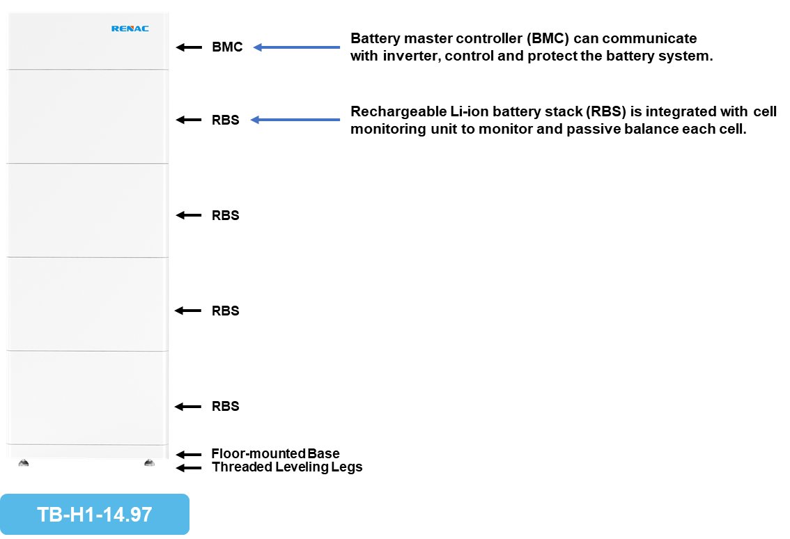
Q1:How is this set of high-voltage batteries made up? What’s the meaning of BMC600 and B9639-S?
A: This battery system consists of a BMC (BMC600) and multiple RBS(B9639-S).
BMC600: Battery Master Controller (BMC).
B9639-S: 96: 96V, 39: 39Ah, Rechargeable Li-ion battery stack (RBS).
Battery master controller (BMC) can communicate with inverter, control and protect the battery system.
Rechargeable Li-ion battery stack (RBS) is integrated with cell monitoring unit to monitor and passive balance each cell.
-
Q2:What battery cell this battery used?
3.2V 13Ah Gotion High-Tech cylindrical cells, one battery pack has 90 cells inside. And Gotion High-Tech is the top three battery cell manufacturers in China.
-
Q3: Turbo H1 Serie Can it be Wall mounted installed?
A: Nope, floor stand installation only.
-
Q4: N1 HV Series What’s the Max. battery capacity to connect with N1 HV Series?
74.9kWh (5*TB-H1-14.97: Voltage Range: 324-432V). N1 HV Series can accept battery voltage range from 80V to 450V.
The battery sets parallel function is under developing, at this moment the max. capacity is 14.97kWh.
-
Q5: Do I need to buy cables externally?
If customer doesn’t need to parallel battery sets:
No, all cables customer needs are in battery package. BMC package contains the power cable &communication cable between inverter &BMC and BMC& first RBS. RBS package contains the power cable &communication cable between two RBSs.
If customer needs to parallel the battery sets:
Yes, we need to send the communication cable between two battery sets. We also suggest you to buy our Combiner box to make parallel connection between two or more battery sets. Or you can add an external DC switch (600V, 32A) to make them parallel. But please mind that when you turn on the system, you have to turn this external DC switch on first, then turn on battery and inverter. Because turning on this external DC switch later than battery and inverter may influence the precharge function of battery, and cause damage on both battery and inverter. (The Combiner box is under developing.)
-
Q6:Do I need to install an external DC switch between BMC and inverter?
Nope, we already have a DC switch on BMC and we don’t suggest you to add external DC switch between battery and inverter. Because it may influence the precharge function of battery and cause hardware damage on both battery and inverter, if you turn external DC switch on later than battery and inverter. If you already install it please make sure the first step is turning on the external DC switch, then turn on battery and inverter.
-
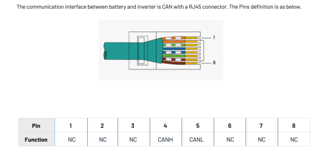
Q7: What’s the pin definition of the communication cable between inverter and battery?
A: The communication interface between battery and inverter is CAN with a RJ45 connector. The Pins definition is as below (Same for battery and inverter side, standard CAT5 cable).
-
Q8:What brand of power cable terminal you use?
Phoenix.
-
Q9: CAN Is this CAN communication terminal resistor necessary to be installed?
Yes.
-
Q10: What’s the Max. distance between battery and inverter?
A: 3 meters.
-
Q11: How about the remotely upgrade function?
We can upgrade the batteries’ firmware remotely, but this function is only available when it works with Renac inverter. Because it is done through datalogger and inverter.
Remotely upgrade the batteries can only be done by Renac Engineers now. If you need to upgrade the battery firmware please contact us and send the inverter serial number.
-
Q12: How can I upgrade the battery locally?
A: If customer use Renac inverter, use a USB disk (Max. 32G) can easily upgrade the battery through the USB port on inverter. Same steps with upgrading inverter, just different firmware.
If customer doesn’t use Renac inverter, need to use converter cable to connect BMC and laptop to upgrade it.
-
Q13: What’s the Max. power of one RBS?
A: Batteries’ Max. Charge / Discharge Current is 30A, Nominal Voltage of one RBS is 96V.
30A*96V=2880W
-
Q14: How about the warranty of this battery?
A: The Standard Performance Warranty for the Products is valid for a period of 120 months from the date of installation, but no more than 126 months from the date of delivery of the Product (whichever comes first). This Warranty covers a capacity equivalent to 1 full cycle per day.
Renac warrants and represents that the Product retains at least 70% of Nominal Energy for the either 10 years after the date of the initial installation or a total energy of 2.8MWh per KWh usable capacity has been dispatched from the battery, whichever comes first.
-
Q15: How does the warehouse manage these batteries?
The battery module should be stored clean, dry and ventilated indoors with a temperature range between 0℃~+35℃, avoid contact with corrosive substances, keep away from fire and heat sources and charged every six months with no more than 0.5C(C-rate is a measure of rate at which a battery discharged relative to its maximum capacity.) to the SOC of 40% after a long time of storage.
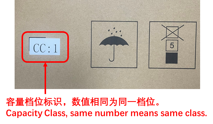
Because battery has self-consumption, avoid battery emptying please send out the batteries you get earlier first. When you take batteries for one customer, please take batteries from same pallet and make sure the Capacity Class marked on these batteries’ carton are same as much as possible.
-
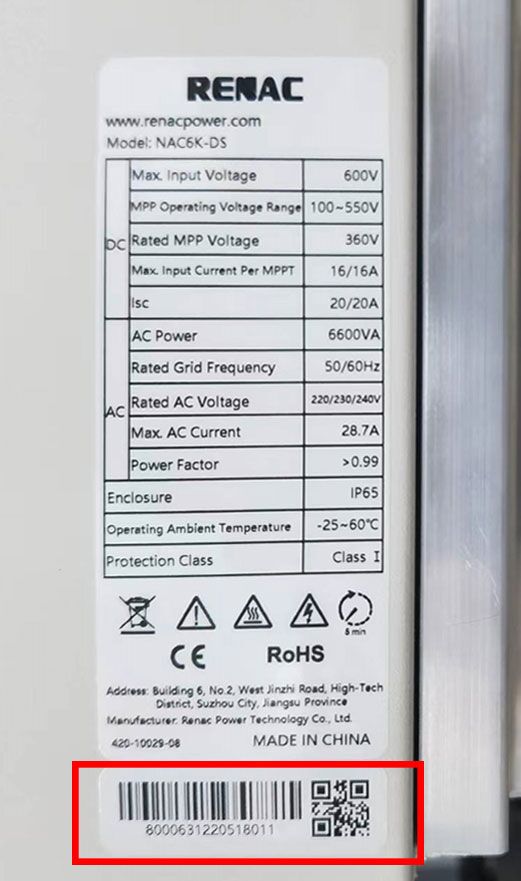
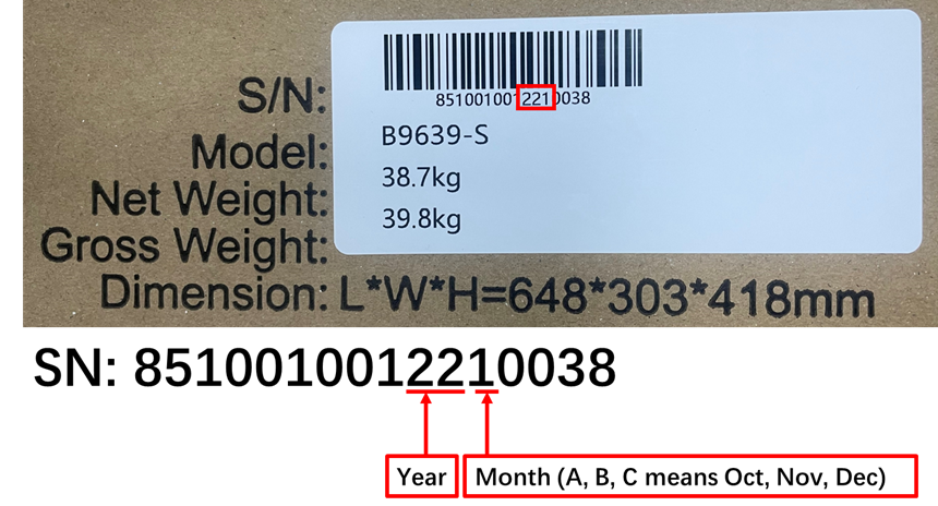
Q16: How can I know when these batteries were produced?
A: From the battery serial number.
-
Q17: What’s the Max. DoD (Depth of Discharge/Discharge Depth)?
90%. Note that the calculation of discharge depth and cycle times is not same standard. Discharge depth 90% does not mean that one cycle is calculated only after 90% charge and discharge.
-
Q18: How do you calculate the battery cycles?
One cycle is calculated for each cumulative discharge of 80% capacity.
-
Q19: How about the current limitation according to temperature?
A: C=39Ah
Charge Temperature Range: 0-45℃
0~5℃, 0.1C (3.9A);
5~15℃, 0.33C (13A);
15-40℃, 0.64C (25A);
40~45℃, 0.13C (5A);
Discharge Temperature Range:-10℃-50℃
No limitation.
-
Q20: Under what situation battery will shut down?
If there is no PV power and SOC<= Battery Min Capacity setting for 10 minutes, Inverter will shut down battery (not totally shut down, like a standby mode which still can be waked up). Inverter will wake up battery during the charging period set in work mode or PV is strong to charge the battery.
If battery lost communication with inverter for 2 minutes, battery will shut down.
If battery has some unrecoverable alarms, battery will shut down.
Once one battery cell’s voltage< 2.5V, battery will shut down.
-
Q21: When working with the inverter, how does the logic of the inverter actively turn on / off the battery operate?
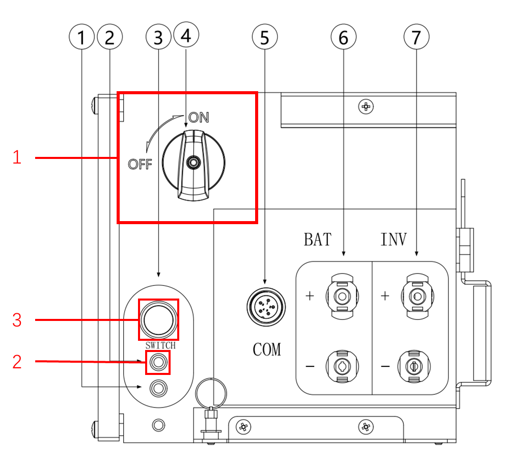
First time turning on inverter:
Just need to turn on On/Off switch on BMC. Inverter will wake up battery if Grid is on or Grid is off but PV power is on. If there is no Grid and PV power, inverter will not wake up battery. You have to turn on battery manually(Turn on On/Off switch 1 on BMC, wait the green LED 2 flashing, then push the Black start button 3).
When the inverter is running:
If there is no PV power and SOC< Battery Min Capacity setting for 10 minutes, Inverter will shut down battery. Inverter will wake up battery during the charging period set in work mode or it can be charged.
-
Q22: Under what situation the emergency charge function will work when battery is connected with inverter?
A: Battery request emergency charging:
When battery SOC<=5%.
The inverter performs emergency charging:
Start charging from SOC= Battery Min Capacity setting (set on display)-2%,the default value of Min SOC is 10%, stop charging when battery SOC reaches Min SOC setting. Charge at around 500W if BMS allows.
-
Q23: Do you have any function to balance the SOC between two battery packs?
Yes, we have this function. We will measure the voltage difference between two battery packs to decide if it needs to run balance logic. If yes we will consume more energy of the battery pack with higher voltage/SOC. Through few cycles normal work the voltage difference will be smaller. When they are balanced this function will stop working.
-
Q24: Can this battery run with other brand inverters?
At this moment we didn’t do compatible test with other brand inverters, but it is necessary we can work with inverter manufacturer to do the compatible tests. We need inverter manufacturer provide their inverter, CAN protocol and CAN protocol explanation (the documents used to do the compatible tests).
-
Q1: How does RENA1000 come together?
RENA1000 series outdoor energy storage cabinet integrates energy storage battery, PCS(power control system), energy management monitoring system, power distribution system, environmental control system and fire control system. With PCS(power control system), it is easy to maintain and expand, and the outdoor cabinet adopts front maintenance, which can reduce the floor space and maintenance access, featuring safety and reliability, rapid deployment, low cost, high energy efficiency and intelligent management.
-
Q2: What RENA1000 battery cell this battery used?
The 3.2V 120Ah cell, 32 cells per battery module, connection mode 16S2P.
-
Q3: What is the SOC definition of this cell?
Means the ratio of the actual battery cell charge to the full charge, characterizing the state of charge of the battery cell. The state of charge cell of 100% SOC indicates that the battery cell is fully charged to 3.65V, and the state of charge of 0% SOC indicates that the battery is completely discharged to 2.5V. Factory pre-set SOC is 10% stop discharge
-
Q4: What is the capacity of each battery pack?
RENA1000 series battery module capacity is 12.3kwh.
-
Q5: How to consider installation environment?
Protection level IP55 can meet the requirements of most application environments, with intelligent air conditioning refrigeration to ensure the normal operation of the system.
-
Q6: What’s application scenarios with RENA1000 Series?
Under common application scenarios, the operation strategies of energy storage systems are as follows:
Peak-shaving and valley-filling: when the time-sharing tariff is in the valley section: the energy storage cabinet is automatically charged and standsby when it is full; when the time-sharing tariff is in the peak section: the energy storage cabinet is automatically discharged to realise the arbitrage of tariff difference and improve the economic efficiency of the light storage and charging system.
Combined photovoltaic storage: real-time access to local load power, photovoltaic power generation priority self-generation, surplus power storage; photovoltaic power generation is not enough to provide local load, the priority is to use battery storage power.
-
Q7: What are the safety protection devices and measures of this product?
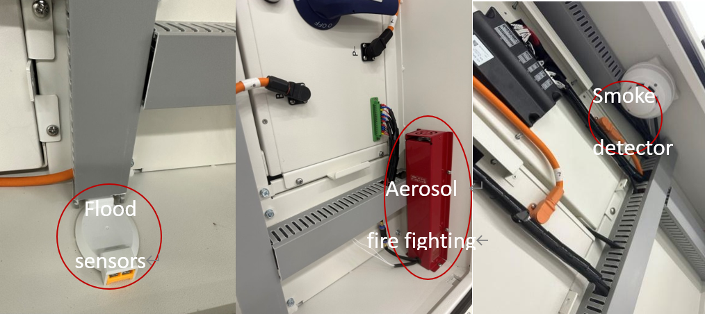
The energy storage system is equipped with smoke detectors, flood sensors and environmental control units such as fire protection, allowing full control of the system’s operating status. The fire fighting system uses aerosol fire extinguishing device is a new type of environmental protection fire fighting product with world advanced level. Working principle: When the ambient temperature reaches the starting temperature of the thermal wire or comes into contact with an open flame, the thermal wire spontaneously ignites and is passed to the aerosol series fire extinguishing device. After the aerosol fire extinguishing device receives the start signal, the internal fire extinguishing agent is activated and quickly produces nano-type aerosol fire extinguishing agent and sprays out to achieve rapid fire extinguishing
The control system is configured with temperature control management. When the system temperature reaches the preset value, the air conditioner automatically starts the cooling mode to ensure the normal operation of the system within the operating temperature
-
Q8: What is PDU?
PDU (Power Distribution Unit), also known as Power Distribution Unit for cabinets, is a product designed to provide power distribution for electrical equipment installed in cabinets, with a variety of series of specifications with different functions, installation methods and different plug combinations, which can provide suitable rack-mounted power distribution solutions for different power environments. The application of PDUs makes the distribution of power in cabinets more neat, reliable, safe, professional and aesthetically pleasing, and makes the maintenance of power in cabinets more convenient and reliable
-
Q9: What is the charge and discharge ratio of the battery?
The charge and discharge ratio of the battery is ≤0.5C
-
Q10: Does this product need maintenance during the warranty period?
There is no need for additional maintenance during the running time. The intelligent system control unit and IP55 outdoor design guarantee the stability of the product operation. The validity period of the fire extinguisher is 10 years, which fully guarantees the safety of the parts
-
Q11. What is the high precision SOX algorithm?
The highly accurate SOX algorithm, using a combination of the ampere-time integration method and the open-circuit method, provides accurate calculation and calibration of the SOC and accurately displays the real-time dynamic battery SOC condition.
-
Q12. What is the smart temp management?
Intelligent temperature management means that when the battery temperature rises, the system will automatically turn on the air conditioning to adjust the temperature according to the temperature to ensure that the whole module is stable within the operating temperature range
-
Q13. What does multi-scenario operations mean?
Four modes of operation: manual mode, self-generating, time-sharing mode, battery backup,allowing users to set the mode to suit their needs
-
Q14. How to support EPS-level switching and microgrid operation?
The user can use the energy storage as a microgrid in case of emergency and in combination with a transformer if a step-up or step-down voltage is required.
-
Q15. How to export data?
Please use a USB flash drive to install it on the device’s interface and export the data on the screen to get the desired data.
-
Q16. How to remote control?
Remote data monitoring and control from the app in real time, with the ability to change settings and firmware upgrades remotely, to understand pre-alarm messages and faults, and to keep track of real-time developments
-
Q17. Does the RENA1000 support capacity expansion?
Multiple units can be connected in parallel to 8 units and to meet customer requirements for capacity
-
Q18. Is the RENA1000 complicated to install?
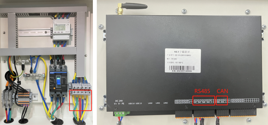
The installation is simple and easy to operate, only the AC terminal harness and the screen communication cable need to be connected, the other connections inside the battery cabinet are already connected and tested at the factory and do not need to be connected again by the customer
-
Q19. Can the RENA1000 EMS mode be adjusted and set according to customer requirements?
The RENA1000 is shipped with a standard interface and settings, but if customers need to make changes to it to meet their custom requirements, they can feedback to Renac for software upgrades to meet their customisation needs.
-
Q20. How long is the RENA1000 warranty period?
Product warranty from the date of delivery for 3 years, battery warranty conditions: at 25℃, 0.25C/0.5C charge and discharge 6000 times or 3 years (whichever arrives first), the remaining capacity is more than 80%
-
Q1: Could you introduce Renac EV Charger?
This is intelligent EV charger for residential and commercial applications, the production including single phase 7K three phase 11K and three phase 22K AC charger .All EV charger is “inclusive”that it is compatible with all brand EVs that you can see in the market, no matter it is Tesla. BMW. Nissan and BYD all other brands EVs and your diver, it all works just that fine with Renac charger.
-
Q2: What type and model of charger port are compatible with this EV charger?
EV charger port type 2 is standard configuration.
Other charger port type for example type 1 , USA standard etc. are optional(compatible ,if needs please remark ) All connector is according to IEC standard.
-
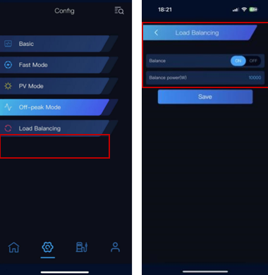
Q3: What is dynamic load balancing function?
Dynamic load balancing is an intelligent control method for EV charging that allows EV charging to run simultaneously with the home load. It provides the highest potential charging power without affecting the grid or household loads. The load balancing system allocates available PV energy to the EV charging system in real time. As a result that the charging power can be instantaneously limited to meet the energy constraints caused by the consumer’s demand , the allocated charging power may be higher when the energy usage of the same PV system is low on the conversely. In addition the PV system will prioritize between home loads and charging piles.
-
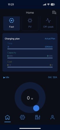
Q4: what is multiple work mode?
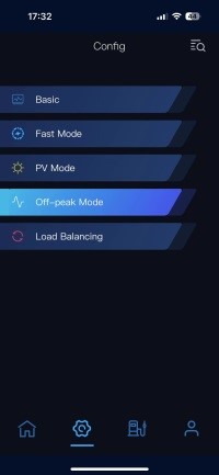
The EV charger provides multiple working modes for different scenarios.
Fast Mode charges your electric vehicle and maximizes the power to meet your needs when you are in a hurry.
PV mode charges your electric car with residual solar energy, improving solar self-consumption rate and providing 100% green energy for your electric car.
Off-peak mode automatically charges your EV with intelligent load power balancing, which rationally utilizes the PV system and grid energy while ensuring that the circuit breaker will not be triggered during charging.
You can check your App about the work modes including fast mode, PV mode, off-peak mode.
-
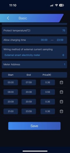
Q5:How to support intelligent valley price charging to save cost?
You can enter the price of electricity and charging time in the APP, the system will automatically determine the charging time according to the price of electricity in your location, and choose a cheaper charging time to charge your electric car, the intelligent charging system will save your charging arrangement cost!
-
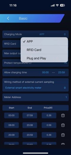
Q6: Can we choose charging mode?
You can set it in APP meanwhile which way is would you like to lock and unlock for your EV charger including APP,RFID card, plug and play.
-
Q7:How to know the charging situation by remote?
You can check it in APP and even have looked all intelligent solar energy storage system situation or change charging parameter
-
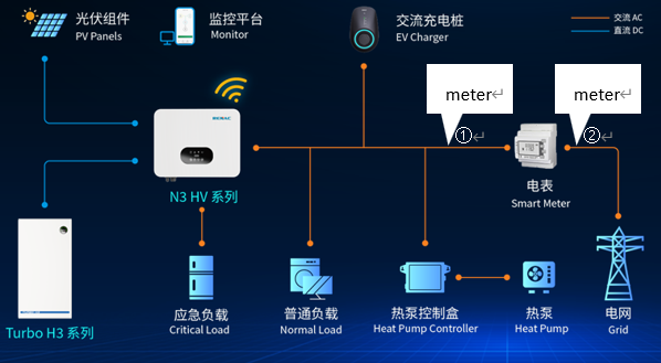
Q8:Is Renac charger compatible with other brands inverter or storage system? If so , need to change else ?
Yes, it is compatible with any brands energy system .But need to installation individual electric smart meter for EV charger otherwise can’t monitoring all data. The meter installation position can be chosen position 1 or position 2 ,as the following picture.
-
Q9: Does any surplus solar energy can be charging?
No, It should be arrived start voltage then can charging, it’s activated value is 1.4Kw(single phase)or 4.1kw(three phase) meanwhile start charging process otherwise can’t start charging when not sufficient power. Or you can set get power from grid for meeting charging demand.
-
Q10: How to calculate the charging time?
If rated power charging is ensured then please reference the calculation as below
Charge time = EVs power / charger rated power
If rated power charging isn’t ensured then you have to check APP monitor charging data about your EVs situation.
-
Q11: Does the protection function for charger ?
This type EV charger have AC overvoltage ,AC undervoltage,AC overcurrent surge protection ,grounding protection ,Current leakage protection, RCD etc.
-
Q12 : Does the charger support multiple RFID cards?
A: The standard accessory includes 2 cards, but only with the same card number. If required, please copy more cards, but only 1 card number is bound, there is no restriction on the quantity of the card.
-
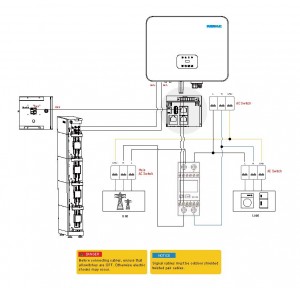
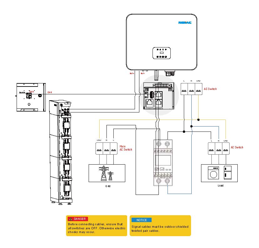
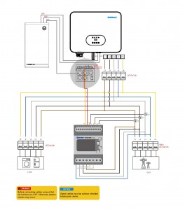
Q1: How to connect a three-phase hybrid inverter meter?
-
Q2: How to connect a single-phase hybrid inverter meter?